
Is it possible to let a laser beam scan over an angle without moving any mechanical parts to deflect the beam? It is. One strategy is to use a very short-pulsed laser beam: A short pulse width means a finite spectral width of the laser (->Heisenberg). A dispersive element like a grating can then be used to automatically diffract the beam into smaller beamlets which in turn can somehow be used to scan or de-scan an object. This technique is called dispersive fourier transformation, although there seem to be different names for only slighly different methods. (I have no experience in this field and am not aware of the current state of the art, but I found this short introductory review useful as a primer.)
Recently, I stumbled over an article that describes a similar scanning technique, but without dispersing the beam spectrally: Multi-MHz laser-scanning single-cell fluorescence microscopy by spatiotemporally encoded virtual source array. First I didn’t believe this could be possible, but apparently it is. In simple words, the authors of the study have designed a device that uses a single laser pulse as an input and outputs several laser pulses, separated in time and with different propagation directions – which is scanning.
Wu et al. from the University of Hong Kong describe their technique in more detail in an earlier paper in Light Science & Applications, and in even more detail in its supplementary information, which I found especially interesting. First, it looked like a Fabri-Pérot interferometer to me, but it is actually completely different and is not even based on wave optics.
The idea is to shoot an optically converging pulsed beam (e.g. coming from an ultra-fast Ti:Sa laser) into an area that is bounded by two mirrors that are almost parallel, but slightly misaligned by an angle α<1°. The authors call these two misaligned mirrors a ‘FACED device’. Due to the misalignment, the beam will be reflected multiple times, but come back once it hits the surface orthogonally (see e.g. the black light path below). Therefore, the continuous spectrum of incidence angles will be automatically translated into a discrete set of mini-pulses coming out of this device, because either a part of the beam gets reflected 14 times, or 15 times – obviously, there is no such thing as 14.5 reflections, at least in ray optics. This difference of 1 in number of reflections makes the 15-reflection beam spend more time in the device, Δt ≈ 2S/c, with S being the separation of the two mirrors, and c the speed of light.
It took me some time to understand how this works and how these pulselets coming out of the FACED device look like, but I have to admit that I find it really cool. The schematic drawings in the supplementary information, especially figures S1 and S5, are very helpful for understanding what is going on.
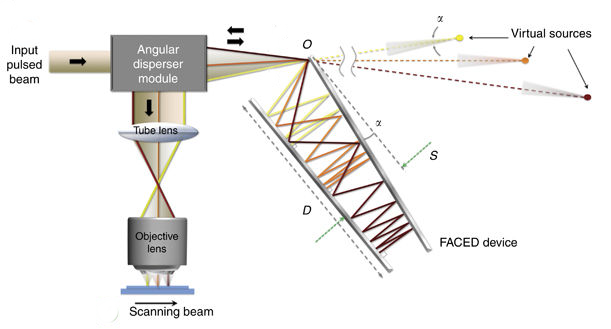 Schematic drawing (adapted) from Wu et al., LS&A (2016) / CC BY 4.0.
As the authors note (without showing any experiments), this approach could be used for multi-photon imaging as well. It is probably true that there are some hidden difficulties and finite size-effects that make an implementation of this scanning technique challenging in practice, but let’s imagine for one minute how this could look like.
Ideally, we want laser pulses that are spaced with a temporal distance of the flourescence lifetime (ca. 3 ns) in order to prevent temporal crosstalk during detection. This would require the two FACED mirrors to be spaced by S = 50 cm, according to the formula mentioned above. Next, we want to resolve, say, 250 points along this fast-scanning axis, which means that the FACED device would need to split the original pulse into 250 delayed pulselets. The input pulsed beam therefore would need to have a pulse repetition rate of ca. 1.3 MHz (which is then also the line scanning frequency), and each of those pulses would need enough power for the whole line scan.
How long would the FACED mirrors need to be? This is difficult to answer, since the answer depends on the divergence angle of the input pulsed beam that hits the FACED device, but I would guess that it needs to be a couple of meters long, given the spacing of the mirrors (50 cm) and the high number of pulselets that are desired (250). (In a more modest scenario, one could envision to split up one pulse of 80 Mhz in only 4 pulselets, thereby achieving multiplexing of additional regular scanning similar to approaches described before.)
However, I would also ask myself whether the created beamlets are not too much dispersed in time, thereby precluding the two-photon effect. And I also wonder how all this behaves like when transitioning from geometric rays to wave optics. Complex things might happen in this regime. – Certainly a lot of work is required to transition this from an optical table to a biologist’s microscope, but I hope that somebody accepts this challenge and maybe, maybe replaces the kHz scanners of typical multi-photon microscopes by a device that achieves MHz scanning in a couple of years.

Pingback: Alvarez lenses and other strangely shaped optical elements | A blog about neurophysiology
And here is a first study using this technique for functional imaging in the brain: https://www.biorxiv.org/content/10.1101/543058v1
Pingback: kHz multiphoton imaging – Labrigger